Dynamic positioning may be defined as "A system that automatically controls a vessel to maintain her position and heading exclusively by means of active thrust".
A DP-capable vessel must have a combination of power, manoeuvrability, navigational ability and computer control in order to provide reliable positioning ability. This forms an integrated system including such elements as the vessel's power plant, propulsion and thrusters, navigational systems, gyro compasses and control computers, while not forgetting the human element.
Control of a DP vessel boils down to control of three of the six freedoms of movement; surge, sway and yaw.
Surge and sway are the two elements comprising the positional control of the vessel, while yaw is control about a vertical rotational axis, or heading. In order to engage these three axes it is necessary to measure the variables concerned, using position references (surge, sway) and gyro compass (yaw). The remaining axes — roll, pitch and heave — are not part of the DP control.
Roll and pitch values must be measured for a separate purpose.
In any DP situation, there will be a reference point within the vessel known as the Centre of Rotation (C of R). This is the spot actually being navigated and can be located at various points. In simple installations the C of R may be placed at the centre of gravity, while other vessels have the C of R located at a specific point, e.g. moonpool, cable lay sheave, "A" frame position or drillship rotary table. Many vessels have more than one C of R available. The DPO selects from a menu exactly where in the vessel he wants the C of R.
Computers
The main control element within the system comprises the computer or computers. The number of control computers will depend upon the level of redundancy available in the vessel, which in turn will relate to the equipment class. In simple terms, single computer systems are fitted in vessels without a critical dependence upon position keeping. These vessels are termed "Equipment Class 1" and thus provide no redundancy. Higher levels of reliability are required for vessels undertaking tasks involving higher risk. These vessels will comply with the requirements for Equipment Class 2 or 3 and their DP systems will feature a level of redundancy.
Dual computer systems feature an online unit plus a standby computer. Extra reliability may be provided by the provision of a triple-computer system, utilising Triple Modular Redundancy, or "Voting". The more stringent requirements of Equipment Class 3 are satisfied by the provision of a minimum of three control computers, at least one of which is located within a separate compartment. In practice this often entails the fitting of a separate back-up DP (usually non-redundant) system to provide an alternative to the main, fully redundant system.
In modern vessels, the DP system may form part of a vessel's integrated control system, communicating by means of a redundant Local Area Network.
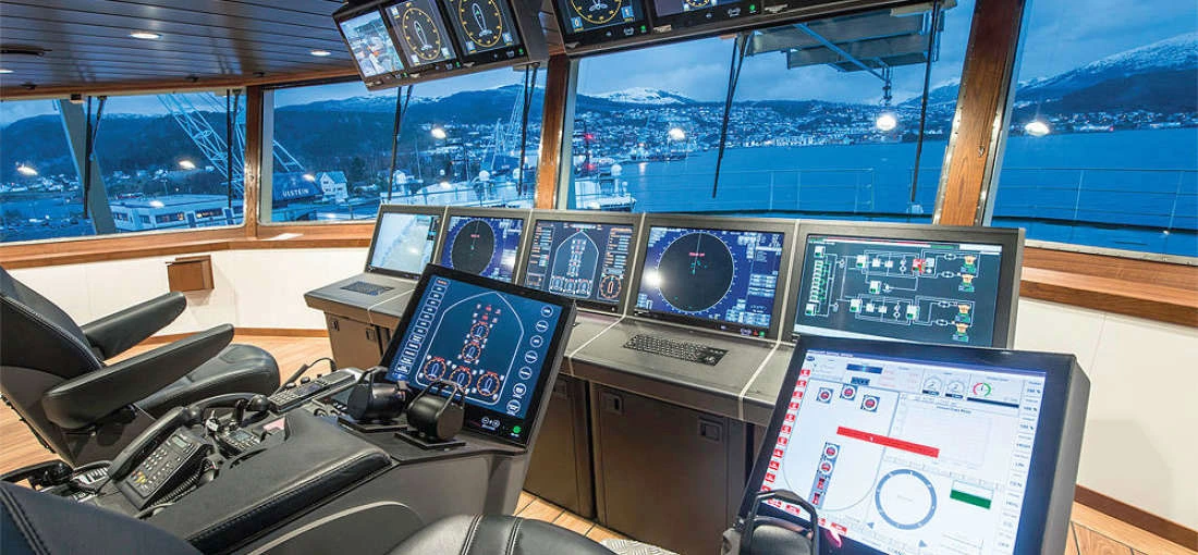
The bridge console or "DP Desk" forms the Man/ Machine Interface (MMI), and is usually located on the bridge. It contains all operational controls, alarm and warning panels and screens, together with the manual joystick manoeuvring controls.
Position reference
A vital part of any DP system is the provision of Position Reference. This is the main area where DP differs from traditional navigation. A DP vessel should be able to maintain her position to within one or two metres of the "set-point" or desired location. This implies that navigational feedback is available providing higher accuracy than this. The navigation systems familiar to navigators are generally of limited value in DP work. Traditional electronic navigation systems are often insufficiently accurate (e.g. Decca Navigator, Loran-C and Global Positioning System (GPS) without differential corrections). DP systems are thus interfaced with Position Reference Systems (PRS) or Position Measuring Equipment (PME) providing greater levels of accuracy and stability.
Five different forms of PRS are in widespread use in DP vessels at the present time. These are DGPS, Hydroacoustic, Artemis, Tautwire and Fanbeam systems. For redundancy purposes, it is important that more than one PRS be used at any time. In fact the requirements of Equipment Class 2 and 3 are the simultaneous use, or pooling, of a minimum of three PRS. Modern DP systems are able to combine two or more PRS inputs to provide a continuous "best-fit" position for the vessel.
DGPS
Differential GPS (DGPS) is an extension of the GPS of satellite navigation. Although GPS is now in widespread use, the accuracy is still deliberately degraded by the US Department of Defence by means of the Selective Availability (SA) applied to the satellite data. This means that the commercial GPS receiver may provide a positional accuracy of 10—100m. Military specification receivers, making use of the P-code, may achieve an accuracy of l-5m, but these systems are not commercially available at the present time.
DP users may avail themselves of a number of DGPS services provided by commercial organisations. Such an organisation will maintain a network of shore-based reference stations, continually observing the positional effects, or errors resulting from the Selective Availability. These errors are then communicated to the vessel by means of a suitable radio link. The ship may then obtain positional data with an accuracy of typically 1—3m.
This then becomes a useful input to the DP, although there are a number of pitfalls of which the DPO must be aware. These include the effects of loss of the data link providing the differential corrections, resulting in an immediate degradation in accuracy.
Despite the problems, DGPS is now regarded as one of the most useful and versatile of PRS for use with DP.
Artemis
Artemis consists of two units working at microwave frequencies. One unit, the "mobile", is located aboard the vessel, while the other unit, the "fixed" station, is located usually on a nearby platform. Each unit carries a double slotted waveguide antenna and, when working, a microwave link is maintained between the two stations. The antennae are servo controlled to track each other against vessel movement, thus allowing a continuous microwave link to be maintained. An interrogation signal originates at the mobile (vessel) unit, and is detected by the fixed station. The mobile receives the reply, the range determined from time-lapse measurement. Bearing is measured directly at the fixed station end, with the bearing data coded into the reply. Maximum range for DP operations is between five to 10 kilometres, although longer ranges have been achieved at the cost of positional accuracy.
Artemis is useful where a relative position may be required, e.g. reference to a moving point. A shuttle tanker may need a reference from a FPSO, which may itself be slowly oscillating in position.
Artemis is an accurate system, but is subject to line- of-sight breaks, antennae roll movement and heat (infra-red) interference.
Hydroacoustic systems
Hydroacoustic Position Reference (HPR) is one of the most prevalent PRS used in conjunction with DP. Two principles are in common use; Long Baseline and Ultra-Short Baseline (USBL). The commonest type is the USBL system. HPR systems are manufactured by Nautronix, Sonardyne and Kongsberg Simrad.
The USBL principle involves the placing on the seabed of an acoustic transponder, which carries its own battery power. This transponder is interrogated by signal transmitted through a hullmounted transducer. This transducer is fitted on the end of a probe projecting four or five metres below the keel. The transducer head detects the reply and die angle or direction of the reply signal is determined using USBL interferometry. The range is determined from time-lapse measurement By this means the three- dimensional location of the transducer can be determined, relative to the location of the transponder.
With any PRS, some allowances must be made. The most obvious is the x/y offset between the sensor (in this case the transducer) and die fixed reference point in the vessel, known as the "Centre of Rotation". Another compensation must be made for the discrepancy between the geodetic vertical and the local (ship-attached) vertical. Since HPR is heavily dependent upon the accurate measurement of this vertical angle, it is important that the attitude (roll and pitch) of the vessel be monitored accurately at all times. This is the function of a vertical reference sensor or unit (VRS or VRU) fitted specifically for that purpose.
The Long Baseline principle involves acoustic interrogation of three or more transponders placed on the seabed around the work location. Once the relative positions of this array have been calibrated, reply ranging from the array will yield an accurate 3D location for the vessel transponder. This avoids the need to use the USBL principles and allows higher accuracy, but there is the need to lay and calibrate the array of transponders before use.
All acoustic systems suffer from a number of problems. Any source of noise in the water will reduce the efficiency of the system, while the accuracy may be compromised by temperature layers, inversions and the resulting refraction. The working range of the system may also be limited, especially in shallower waters. Nevertheless, HPR is extensively used offshore, not only for DP purposes, but also for marking and location of underwater hardware, ROVs, etc.
Tautwire
Tautwire systems differ from all other PRS in that they are chiefly mechanical in nature. A typical tautwire system consists of an A- frame or davit assembly located on deck. A tension winch arrangement carries a length of thin wire rope with a heavy depressor weight. With the A-frame or davit extended over the side of the vessel, the weight is lowered to the seabed and the unit switches to a tension mode. Thereafter, the length of wire deployed or water depth combined with the wire angles determine the position of the vessel relative to the position of the weight. Many vessels are fitted with two tautwire systems, one on each side of the ship.
Of necessity, a tautwire system is limited in many ways. Maximum range is dependent upon water depth, as is system accuracy. The system is limited to a rated maximum depth of typically 300-400m. The system is limited to providing a relative position for a vessel in a fixed location. The system may be influenced by strong currents. If the vessel has to shift location then the tautwire weight must be reset. Nevertheless, the tautwire is a popular, accurate and frequently used system.
Fanbeam
The Fanbeam system is an optical laser radar system manufactured by MDL of Aberdeen. It consists of a projector unit, or scanner, mounted at a high point within the vessel, communicating with a control panel in the bridge. An optical reflector (survey prism unit) is placed at a fixed point, e.g. on a nearby platform, and the unit continually scans across the bearing of the target reflector while transmitting laser pulses. Distance is determined by echo ranging, while bearing is read from a shaft encoder within the scanner unit.
Fanbeam is fast becoming a very popular PRS for DP purposes. It is accurate and simple to set up and use, but has limited range (l-2km) while range and efficiency is impaired by poor visibility, rain or simply from dirt on the lens. It is also vulnerable to line-of-sight breaks.
Heading and attitude reference. Vessel heading is determined from a standard gyro installation. In many vessels, a duplicate gyro is fitted for redundancy purposes, while the higher equipment class vessels may have three, in order to provide a facility for "voting". Without this latter facility, there is the problem of determining which of two gyros has failed when there is a discrepancy, and the errant unit is not obvious.
Vessel attitude is a necessary feedback into the DP system. It has been mentioned above that the value of roll and pitch must be allowed for in the computations for position obtained from HPR and, in some cases, tautwire systems. Both these systems generate positional data derived from angular measurements from the vertical. In order to provide a geodetic datum, the vessel is provided with one or more Vertical Reference Sensors (VRS), or electronic inclinometers.
Environment reference
Any DP system is enabled to read data from one or more transmitting anemometers or wind sensors. This data is used in a number of ways. The DP system uses information on wind direction and strength to calculate compensation forces necessary. Further, gusting conditions are countered by the wind sensors in a facility known as "Feed Forward". With wind feed forward, the DP is able rapidly to compensate for radical changes in wind speed and/ or direction. Another function of the wind sensors is to enable the DP system to calculate a "weathervane" (or minimum power) heading. Some vessels (e.g. shuttle tankers) may operate continuously in a weathervane mode, and would rapidly lose DP capability if the environmental forces were allowed to attack the vessel from other directions.
ropulsion elements
In order to provide a DP function, the vessel must be equipped with an adequate spread of propellers and thrusters. For DP purposes, a minimum of three thrusters is required, and most vessels are fitted with more than this minimum. A monohull vessel may be fitted with twin screws and rudders, a stern tunnel thruster and three bow tunnel thrusters. A semi- submersible drilling rig may be fitted with six or eight azimuth thrusters. Many variations are possible. In some vessels the rudders are DP active, to provide transverse forces aft, while in other vessels the rudder is not controlled by the DP system.
Power plant
Vital to the safety of any DP operation is the continuity of the power supply. The power plant must always be considered to be an integral part of the vessel's DP system. Any interruption in the supply of power can have knock-on effects on the positioning capability of the vessel. DP vessels are particularly vulnerable to blackout or part-blackout situations. Many DP-capable vessels are of diesel-electric configuration. In vessels of this type power is generated on a power-station basis and supplied to the vessel through switchboards. Thrusters and propulsion plant will often run on High Voltage (HV), typically 6kV or 6-6kV, while the remainder of the vessel will be configured for 440V, 380V or 240V supply, or a combination of voltages.
Diesel-electric plant is particularly suited to DP operations, because of its ability to react rapidly to large, often unpredictable, changes in load. The number and configuration of alternators "on the board" may be varied to suit the conditions and demand of the moment, with the required level of reserve power. Switchboards may be split into two or more sections, each supplying a proportion of the propulsion plant. In Equipment Class 2 and 3 vessels the loss of one section should not result in the loss of position or heading. A typical power distribution layout for a multi-role support vessel is shown in figure 9 overleaf.
The above description covers the hardware making up a typical DP system. It is important to realise that DP is very much a whole-ship function, covering operational patterns and procedures, documentation, personnel competency and many other factors. Further information upon specific vessel types and operational methods is contained in section 10 of this monograph. All modern DP control systems utilise a system of mathematical modelling in order to improve and optimise the positioning ability of the vessel. This involves the system fine-tuning itself to the conditions over a period of up to 30 minutes. During this initial period, the vessel positioning will not be as stable as may be observed later, once the settling period is complete. This is why a period of time is often required once the vessel has positioned on the worksite before commencing the operation. This precaution should not be neglected.